Follow-On Current from AC SourcesSURGE ABSORBERS
When DC is the power supply, follow-on current occurring in gas discharge tubes for AC sources is easy to understand.
In the figure 12, the only difference is that the power supply voltage (Vo) changes with time. As shown on the previous page, when the power supply voltage is shown as Vo(t), the output power characteristics are displayed as follows:
With “v” being the voltage at the power out terminal, and “I” the current of the circuit,
\[ v = Vo\begin{pmatrix}t\end{pmatrix} - R \cdot I ・・・(2)\]
Vo(t) will vary with time, so when displaying the above equation on a graph, it will appear as in the figures below in the shaded areas. Then when Vo(t) is shown as:
\[ Vo \begin{pmatrix}t\end{pmatrix} = Vo\sin \omega t ・・・(3)\]
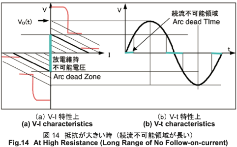
When the power supply voltage becomes 0 (zero cross), there is a short time where the voltage range and time range of the power supply output and discharge tube V-I curve do not intersect. For an AC power supply, because there is always a zero crossing of the supply's voltage, it is easier to stop the discharge than in the case of holdover. In the vicinity of the zero crossing, it is impossible to maintain the discharge since the current to the discharge is cut off. The discharge is then halted by the ionized gas molecules returning to their normal state.
Because the terminal voltage does not exceed the direct current break down voltage, if the discharge is halted, it will not be able to start again.
However, if the gas molecules remain ionized during this period and voltage is again applied to both terminals of the discharge tube (enters the cycle of opposite voltage), this newly applied voltage will not allow the discharge to end and it will continue in the discharge mode. This is follow-on current for alternating current. When this type of follow-on current occurs, the tube stays in a discharge mode and the glass of the tube will begin to smoke, melt and possibly ignite.
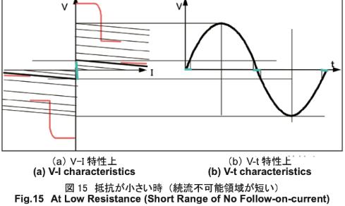
It is important to utilize a resistance in series that is sufficiently large enough to prevent follow-on-current from occurring according to the conditions of the alternating current.
With 1Ω and 3Ω resistance, results are the same as those in photo 2, as follow-on-current is disrupted and discharge is stopped.
For AC power sources, the resistance value that is connected in series with the discharge tube is small in comparison to DC sources.
If the series resistance is 0.5Ω or greater, it should be sufficient; however, for safety, a value of 3Ω (for 100V) or greater is recommended.
In addition, there is a method to use a varistor in series that acts as a resistor. In this case, the varistor must have an operating voltage greater than the AC voltage and be placed in a series with the discharge tube. Unlike the resistor, discharge will be stopped without follow-on current occurring during the first half of the wave.
Selection of varistor voltage:
- For AC 100V : V1mA ≧ 220V
- For AC 200V : V1mA ≧ 470V
Our DSANR and DSAZR Series are made for power supplies and are designed to prevent follow-on current.
At risk applications of holdover or follow-on-current:
- 1. Holdover
- Circuits using DC power sources
- 2. Follow-on current
- Circuits using AC power sources