 P.T. SMELTING's Site |
Introduction
|
PTS began commercial production on May 28,
1999. In the calendar year 2001, PTS produced
214,000 tonnes of cathodes, 7% over design
capacity. This was a most commendable achievement,
considering that the locally recruited workforce
started with virtually no experience of copper
smelting or refining.
In June 2001, one year from the start of
commercial operations, the PTS cathode received
Grade "A" accreditation from the
London Metal Exchange ("LME") the
hallmark of quality in the Copper Industry.
The production capacity was increased step by step.
In 2009, 1,060 thousand tons of concentrates were treated and
300 thousand tons of new anodes were produced.
The Gresik plant was constructed at the green field,
where there was nothing at all other than the soil and grass.
The construction work was governed by CHIYODA Corporation,
one of the engineering companies of Mitsubishi Group, on EPC (Engineering,
Procurement and Construction) base.
Total construction cost except utility plant was US$ 500 million.
BOC spent around US$ 100 million to construct the utility plant at the same site,
from where all of necessary oxygen and power are provided to PTS over the fence.
The additional cost for the expansion was only US$ 26 million.
Many visitors have seen and praised the operation,
however PTS's finest accolade came from
Dr. H. H. Kellogg, Professor Emeritus, Columbia
University following an extensive visit in
July 2000. He summarized his assessment
with the words...Truly a Plant for the
21st Century. His full comments can
be found in his letter, published in JOM,
Vol. 52, No.11, November 2000.


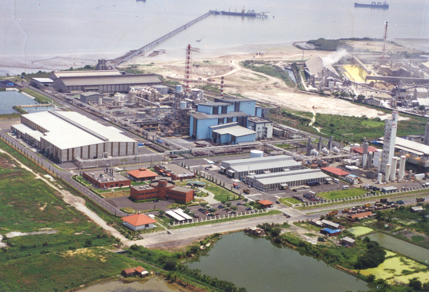 |
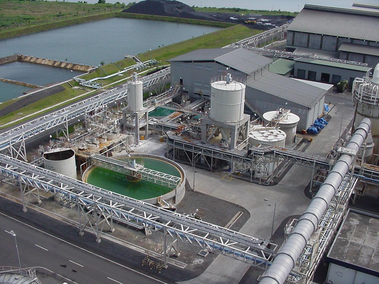
Major FacilitiesThe copper smelting and refining complex
consists of the smelter itself, which produces
copper anodes and process off-gases high
in SO2, the sulphuric acid plant, the tankhouse,
and other necessary infrastructure within
the site boundary, including a waste water
plant, a jetty & wharf and material handling
facilities. Oxygen for the smelting process
is procured from an outside supplier. Steam
from the smelter waste heat boiler is sent
to a neighboring power generation plant which
returns the condensate to the smelter. |


Operational parameters are shown in the following
table.
Concepts are simillar to the process operating
in Naoshima with certain exceptions.
| Description | Unit | DESIGN | In 2009 |
| [S-Furnace] | |||
| Conc. Feed Rate Reverts, etc. Coal |
T/H T/H T/H |
86.1 0.7 3.1 |
142.5 3.0 3.0 |
| Silica Feed Rate Limestone Feed Rate Return C-slag |
T/H T/H T/H |
12.9 0.2 10.5 |
16 - 10 |
| Matte Production Slag Production |
T/H T/H |
46.2 50.1 |
55 87 |
|
Nm3/H Nm3/H Nm3/H % |
25,900 13,300 39,200 48.0 |
17,500 24,500 42,000 66.8 |
| [C-Furnace] | |||
| Limestone Feed Rate Anode Scrap Feed Rate Coolant Feed Rate |
T/H T/H T/H |
3.3 5 3 |
5 8 |
| Blister Production |
New T/H Total T/H |
26.8 31.8 |
35 40 |
| C-slag Production |
New T/H Total T/H |
10.5 13.5 |
10 18 |
|
Nm3/H Nm3/H Nm3/H % |
27,100 3,800 30,900 30.8 |
26,000 5,200 31,200 34.1 |
| [Furnace Offgas] | |||
| S-furnace |
WNm3/min DNm3/min SO2% |
670 600 30.1 |
680 620 48.5 |
| C-furnace |
WNm3/min DNm3/min SO2% |
510 490 21.7 |
520 510 25.8 |